Pre Engineered Buildings
At SBSPL, we have always focused on providing durable, cost-effective and superior quality buildings. We offer complete turnkey steel construction solutions ranging from detailing to onsite erection along with maintenance and after sales services, all under one roof. We are expert in Pre engineered building & Pre engineered steel building Construction.
Our advanced computer design, planning and manufacturing provides enhanced project control, complete structural analysis, faster field erection, accurate project pricing and cost predictability. Our Pre-engineered buildings are custom-designed solution to meet the need of customer. All buildings are design & constructed according with the Indian & International Standard.
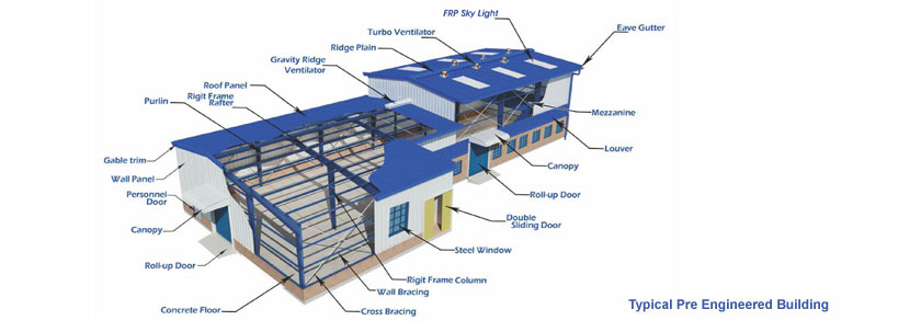
Typical Pre Engineered Building
We designed & manufactured our buildings in according to the latest edition of the following codes:
- Low-Rise Building System Manual (MBMA) - Metal Building Manufacturers Association Inc, USA
- Manual for Steel construction, Allowable Stress design (AISC)- American Institute of Steel Construction Inc, USA.
- Cold Formed Steel Design Manual (AISI) – American Iron and Steel Institutes , USA.
- IS : 800 : 2007
- IS 875
Pre Engineered Buildings are widely accepted with multiple Industry segments such as Automobiles, Railways, Warehousing, Power, Commercial Complexes, Manufacturing, etc., we are well versed with the unique requirements of each. Above all, our highly skilled and experienced team operates with the zeal to translate smart engineering into smart buildings; buildings that can be customized and tailor-made to meet your needs.
Typical Pre Engineered Building :-
- Right Frame column
- Main Frame Rafter
- Purlin
- Mezznine Beam
- Mezzanine Joist
- Roof Monitor
- Angle /Rod Bracing
- Roof Sheeting
- Wall Cladding
- Eaves Gutter
- Corner Trim
- Ridge vents
- Turbo Vents
- Translucent sheets
- Insulation
- Crane Beam
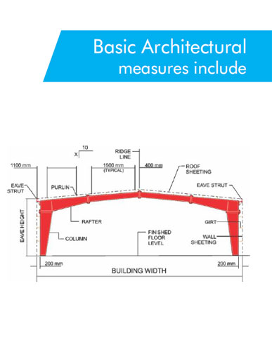
Basic Architectural Measure Include:-
|
|
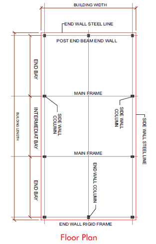
Building Width : |
Building width is defined as the distance between the eave strut of both side wall. |
| Building Length : |
Building length is defined as the distance between the outside flanges of both end walls. |
End Bay Length : |
The distance from the outside of End wall girts to the center line of the columns of the first interior rigid frame. |
Interior Bay Length : |
Is the distance between the center lines of columns of two adjacent interior rigid frames. Most economical range of interior bays is the 7.5m and 8.5m. however, the common interior bay lengths in the industry are 6, 7.5, 8 and 9 and 10m. Maximum economy, limit the end bay length to 6 meters or less and use bypass end walls girts. |
Building Height : |
Eave height is the distance from finish floor level to the top of the outer point of the eave purlin. Clear height is the distance from finish floor level to the knee where the column and rafter connect. |
Roof Slop (X/10) : |
This is the angle of the roof with respect to the horizontal. The most common roof slope in the area is 0.5/10 and 1/10. However any practical roof slope is possible. Steel LineIs the plane of the out of secondary "Z" and "C" members. |
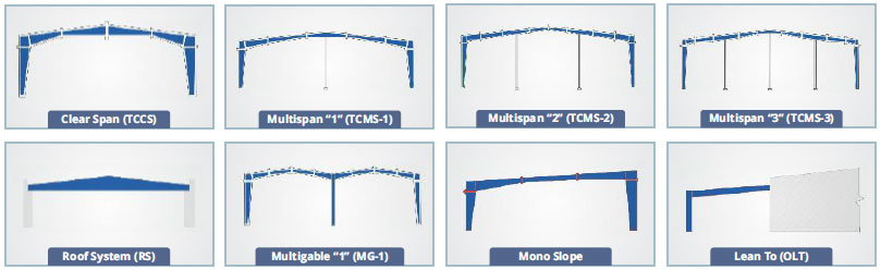
TYPE OF FRAME :
SBSPL, caters to the customized requirements of its clients viz. building type, space efficiency, building utility and designing flexibility. The buildings are built using various frame options.
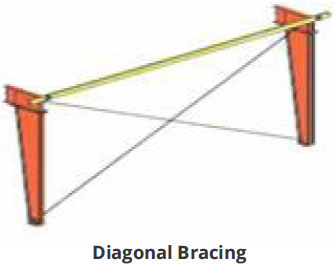
DIAGONAL BRACING SYSTEM
This member is design to ensure the stability of the building against forces in the longitudinal direction due to wind, crane, earthquake etc.
Bracing systems all horizontal loads on a structure must eventually be carried to column based and then to the building substructure (foundation and ground slabs). Horizontal loads result from the action of wind forces seismic (earth quake) forces and overhead cranes on the building structure.
Diagonal Bracing is used in the roofs and walls of buildings to transfer wind forces to the building substructure. Standard bracing system commonly used is galvanized cable strands, solid smooth rods, flat bars, ms pipe or angles.
Diagonal Angle Bracing is used to transfer longitudinal horizontal loads of traveling overhead cranes to substructure when the capacity of these cranes exceeds 20 MT. They are also used as wall bracing in very high buildings.
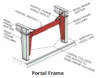
Portal Frames are used in exterior sidewalls or between the interior columns of Multi Span / Multi Gable buildings when diagonal bracing is not allowed because of a requirement for clear unobstructed space. Portal frames are made from built-up columns and beams. Their columns flanges are stitch bolted to the webs of the rigid frame columns and extend down to 150 mm above F.F.L. care must be taken to ensure that the bottom of the portal frame beam is higher than the required unobstructed height.